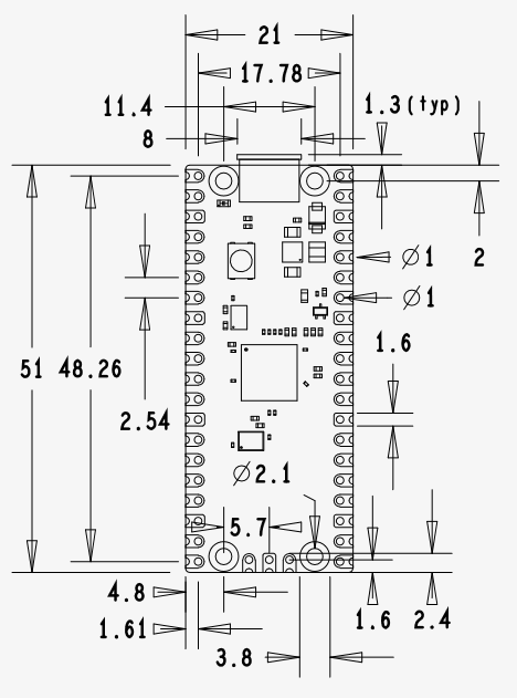
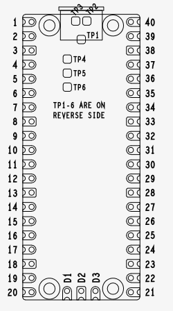
.
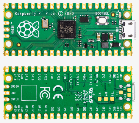
Paspberry Pi Pico


| 項目 | 内容 |
|---|---|
| 搭載マイコン | RP2040(Dual-core cortex M0+、最大動作周波数133MHz) |
| 仕上りパッケージ | DIP40 |
| フラッシュメモリ | 2MB |
| SRAM | 264KB |
| USB | USB 1.1 ホスト/デバイス両対応 |
| I/O | GPIOx26(ADCx3含む) |
| その他 | UARTx2、I2Cx2、SPIx2、PWMx16、PIOx8 |
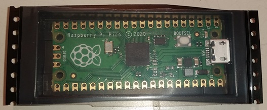
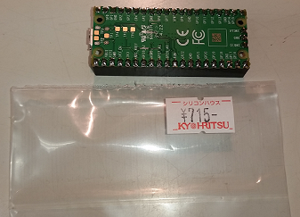
シリコンハウスで 715円(税込)でした。(2023.03)
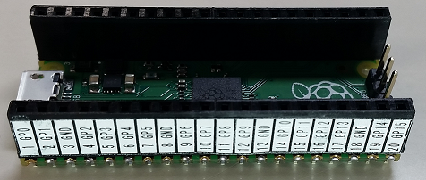
ピンソケットを実装して、ARDUINO風にしてみました。
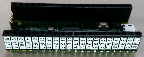
ARDUINO IDE でテストしてみた。
★最速でのon/off(digitalWrite, loop使用)
プログラム
// Raspberry Pi Pico パルス出力テスト 2023.04.09
// digitalWrite, loop バージョン
const int32_t PulseOutPin = 16; // GP16
void setup() {
// put your setup code here, to run once:
pinMode(PulseOutPin, OUTPUT);
}
void loop() {
// put your main code here, to run repeatedly:
digitalWrite(PulseOutPin, HIGH);
digitalWrite(PulseOutPin, LOW );
}
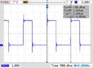
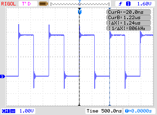
★最速でのon/off(digitalWrite, while使用)
プログラム
// Raspberry Pi Pico パルス出力テスト 2023.04.09
// digitalWrite, while バージョン
const int32_t PulseOutPin = 16; // GP16
void setup() {
// put your setup code here, to run once:
pinMode(PulseOutPin, OUTPUT);
}
void loop() {
// put your main code here, to run repeatedly:
while(1){
digitalWrite(PulseOutPin, HIGH);
digitalWrite(PulseOutPin, LOW );
}
}
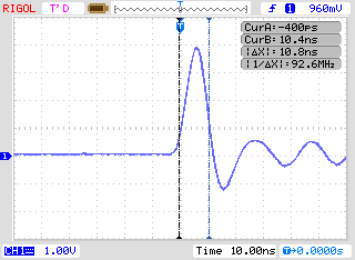
★最速でのon/off(gpio_put, loop使用)
プログラム
// Raspberry Pi Pico パルス出力テスト 2023.04.09
// gpio_put, loop バージョン
const int32_t PulseOutPin = 16; // GP16
void setup() {
// put your setup code here, to run once:
pinMode(PulseOutPin, OUTPUT);
}
void loop() {
// put your main code here, to run repeatedly:
gpio_put(PulseOutPin, HIGH);
gpio_put(PulseOutPin, LOW );
}

★最速でのon/off(gpio_put, while使用)
プログラム
// Raspberry Pi Pico パルス出力テスト 2023.04.09
// gpio_put, while バージョン
const int32_t PulseOutPin = 16; // GP16
void setup() {
// put your setup code here, to run once:
pinMode(PulseOutPin, OUTPUT);
}
void loop() {
// put your main code here, to run repeatedly:
while(1){
gpio_put(PulseOutPin, HIGH);
gpio_put(PulseOutPin, LOW );
}
}

★最速での位相差パルス出力(gpio_put, while使用)
プログラム
// Raspberry Pi Pico 位相差パルス出力テスト 2023.04.09
// multi core
// core0 gp16,17 pulse output
// core1 led blink 25
// core1 gp0 SWPin pullup
// Used gpio_put Version fast pulse output
// shori2に渡す変数をセマフォにより管理
#include "pico/multicore.h" // multicore lib
const int32_t pinPA = 16; // A相
const int32_t pinPB = 17; // B相
const int32_t ledPin = 25; // the number of the LED pin RPi Pico LED = 25
const int32_t MaxCount = 2; // Phase Max Count Maxに達したらUD極性反転,count reset
const int32_t SWPin = 0; // start sw
const int32_t PState[4][2] ={ // 位相差パルスの状態
{ LOW, LOW},
{HIGH, LOW},
{HIGH, HIGH},
{ LOW, HIGH}
};
// 排他処理用のセマフォ
static semaphore_t sem;
int32_t Phase = 0; // Phase State
int32_t Count = 0; // Phase Counnt
int32_t UD = 0; // UP=0 / DOWN=1
volatile int32_t _waitc; // wait counter
int ledState = LOW; // ledState used to set the LED
long interval = 30; // interval at which to blink (milliseconds)
unsigned long previousMillis = 0; // will store last time LED was updated
uint32_t start_f = 0; // start flag 0:none , 1:run, 2:finish
void setup() {
// セマフォを初期化
sem_init(&sem, 1, 1);
pinMode(pinPA, OUTPUT);
pinMode(pinPB, OUTPUT);
gpio_put(pinPA, LOW);
gpio_put(pinPB, LOW);
pinMode(SWPin , INPUT ); // 入力ピン
gpio_pull_up(SWPin); // 入力ポートのプルアップ
}
void loop() {
shori1(); // 全速力で行ったり来たりプログラム
// shori2(); // 一定数パルス出力後停止
}
// 全速力で行ったり来たりプログラム
void shori1(){
while(1){
gpio_put(pinPA, PState[Phase][0]);
gpio_put(pinPB, PState[Phase][1]);
if(UD == 0){
Phase = (Phase + 1) & 0x03;
if(Phase == 0) Count++;
}else{
Phase = (Phase - 1) & 0x03;
if(Phase == 0) Count--;
}
if(Count == MaxCount) UD = 1;
if(Count == 0 ) UD = 0;
// // delayなし 943kHz
}
}
// 一定数パルス出力後停止
void shori2(){
UD = 0; // up pulse
while(1){
// セマフォから許可を要求。許可が得られるまで待機
sem_acquire_blocking(&sem);
start_f = 0;
// セマフォの許可を解除
sem_release(&sem);
while(digitalRead(SWPin) & 0x01); // SW PinがLOWになるのを待つ start sw
// セマフォから許可を要求。許可が得られるまで待機
sem_acquire_blocking(&sem);
start_f = 1;
// セマフォの許可を解除
sem_release(&sem);
for(Count = 0; Count < 200000; Count++){ // 200000 / 4state = 50000
pulse
gpio_put(pinPA, PState[Phase][0]);
gpio_put(pinPB, PState[Phase][1]);
if(UD == 0){
Phase = (Phase + 1) & 0x03;
}else{
Phase = (Phase - 1) & 0x03;
}
for(_waitc = 0; _waitc < 29; _waitc++); // 84kHz
}
// セマフォから許可を要求。許可が得られるまで待機
sem_acquire_blocking(&sem);
start_f = 2;
// セマフォの許可を解除
sem_release(&sem);
while(digitalRead(SWPin) & 0x01); // SW PinがLOWになるのを待つ start sw
UD = (UD +1) % 2; // UP/DOWN 切り替え
delay(1000);
}
}
//--------------------------------------------------------------------------------------------------------------
// Core1 Program
void setup1() {
// set the digital pin as output:
pinMode(ledPin, OUTPUT);
}
void loop1() {
// here is where you'd put code that needs to be running all the time.
unsigned long currentMillis = millis();
int32_t _sw;
// セマフォから許可を要求。許可が得られるまで待機
sem_acquire_blocking(&sem);
_sw = start_f;
// セマフォの許可を解除
sem_release(&sem);
switch(_sw){ // start_f core0と1の共通の変数がぶつかるとうまく動かない
case 0:
interval = 30;
break;
case 1:
interval = 500;
break;
case 2:
interval = 100;
break;
}
if (currentMillis - previousMillis >= interval) {
previousMillis = currentMillis;
if (ledState == LOW) {
ledState = HIGH; // 点灯
} else {
ledState = LOW; // 消灯
}
gpio_put(ledPin, ledState);
}
}
処理1のオシロ画像
(2パルスで折り返し)
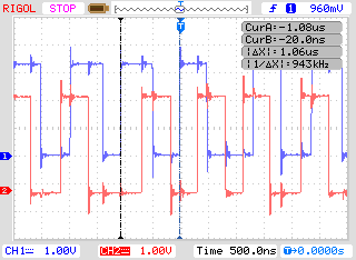
ついでにマルチコアでLED点滅してみた。
処理2では、セマフォを使用して変数の受け渡しもテスト。
(セマフォを使用しなかったら、うまく変数の受け渡しができなかった。)
Paspberry Pi Pico 2
RP2350 150MHz
Arduinoにて実験
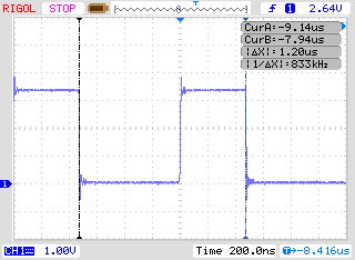
☆ case 1
void loop() {
// 1.2us about Low: 0.66us, High: 0.44us
digitalWrite(OutPin, HIGH);
digitalWrite(OutPin, LOW);
}
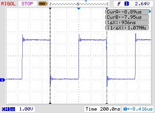
☆ case 2
void loop() {
// 936ns about Low: 0.44us, High: 0.44us
while(1){
digitalWrite(OutPin, HIGH);
digitalWrite(OutPin, LOW);
}
}
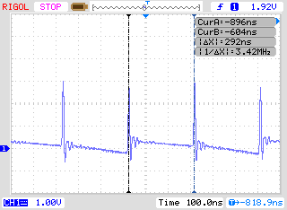
☆ case 3
void loop() {
// 292ns about Low: 290ns, High: 10ns
gpio_put(OutPin, HIGH);
gpio_put(OutPin, LOW);
}
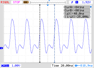
☆ case 4
void loop() {
// 40ns about Low: 20ns, High: 20ns
while(1){
gpio_put(OutPin, HIGH);
gpio_put(OutPin, LOW);
}
}
☆ case 5
void loop() {
// 240ns about Low: 120ns, High: 120ns
while(1){
gpio_put(OutPin, HIGH);
n = digitalRead(InPin);
gpio_put(OutPin, LOW);
n = digitalRead(InPin);
}
}
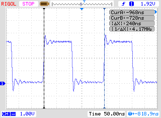
☆ case 6
void loop() {
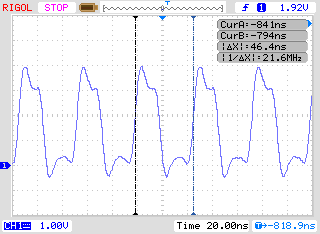
// 46.4ns about Low: 23ns, High: 23ns
while(1){
gpio_put(OutPin, HIGH);
n = gpio_get(InPin);
gpio_put(OutPin, LOW);
n = gpio_get(InPin);
}
}
